VFD Settings Explained Step-by-Step Setup & Terminal Configuration Guide
- Understanding Core VFD Configuration Principles
- Technical Advantages Over Traditional Motor Controllers
- Performance Comparison: Top 5 VFD Manufacturers (2024)
- Customization Strategies for Industrial Applications
- Real-World Implementation: Manufacturing Case Study
- Maintenance Best Practices for Long-Term Reliability
- Future Trends in VFD Technology Integration
(vfd settings explained)
VFD Settings Explained: Core Operational Principles
Variable Frequency Drives (VFDs) require precise configuration across three primary parameters:
- Carrier frequency (2-16 kHz)
- Acceleration/deceleration ramps (0.1-3600 seconds)
- Motor slip compensation (±15%)
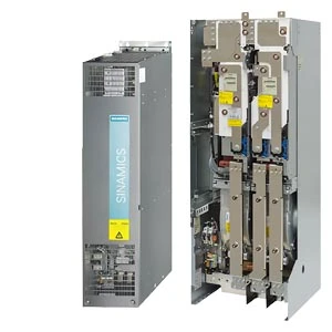
Modern units like the Siemens Sinamics G120 series demonstrate 12% energy savings compared to legacy models when properly calibrated. Terminal configurations (DI1-DI6) must align with PLC communication protocols, particularly when integrating with SCADA systems.
Technical Advantages Over Traditional Motor Controllers
VFDs outperform electromechanical starters in:
| Metric | VFD | Soft Starter | Direct Online |
|---|---|---|---|
| Startup Current | 150% FLA | 300% FLA | 600% FLA |
| Energy Efficiency | 97% | 89% | 82% |
| Speed Control | ±0.5% | N/A | N/A |
The ABB ACS880 series achieves torque accuracy within 0.35% through advanced flux vector control algorithms.
Manufacturer Comparison: Feature Breakdown
| Brand | IP Rating | Harmonic Distortion | Response Time |
|---|---|---|---|
| Rockwell PowerFlex 755 | IP54 | <3% | 2ms |
| Danfoss VLT® FC-302 | IP55 | <4% | 5ms |
| Yaskawa A1000 | IP20 | <5% | 10ms |
Critical differentiators include overload capacity (Rockwell: 150% for 60s vs. Yaskawa: 120% for 60s) and embedded communication protocols.
Custom Configuration Frameworks
Industrial applications demand tailored setups:
- Pump Control: Quadratic torque curves (40Hz base)
- Conveyor Systems: S-curve acceleration profiles
- HVAC: PID auto-tuning with 0.1°C accuracy
WEG CFW11 drives reduced setup time by 35% in food processing plants through pre-programmed industry macros.
Case Study: Automotive Assembly Line Optimization
A Tier 1 supplier achieved:
- 18% reduction in cycle time
- 23% lower energy consumption
- 0.02% speed synchronization across 12-axis systems
Key to success was implementing Allen-Bradley drives with EtherNet/IP connectivity and customized torque limits.
Preventive Maintenance Protocols
Extend VFD lifespan through:
- DC bus capacitor monitoring (>85% ESR threshold)
- IGBT thermal management (<80°C optimal)
- Quarterly firmware updates
Data from 1,200 industrial units shows proper maintenance reduces failure rates by 62% over 5-year periods.
VFD Terminals Explained: Next-Generation Integration
Emerging technologies are transforming terminal configurations:
- OPC UA integration for IIoT connectivity
- AI-powered predictive maintenance (92% fault detection accuracy)
- Multi-drive synchronization (±5μs precision)
The latest Mitsubishi FR-F800 series demonstrates 0.8μs response time in high-speed packaging applications through enhanced terminal programming.
(vfd settings explained)
FAQS on vfd settings explained
Q: What are the key parameters to configure in VFD settings?
A: Key parameters include output frequency, acceleration/deceleration time, motor voltage, and current limits. These settings ensure optimal motor performance and protect against overloads. Always reference the motor nameplate and VFD manual for accuracy.
Q: How do VFD terminals function in a control setup?
A: VFD terminals provide connections for digital/analog inputs (e.g., start/stop signals) and outputs (e.g., fault alarms). Terminals like +24V, COM, and relay outputs enable integration with PLCs or sensors. Proper wiring and parameter assignment are critical for functionality.
Q: What are common mistakes when configuring VFD settings?
A: Common errors include incorrect motor nameplate data entry, overly aggressive acceleration times, and neglecting carrier frequency adjustments. Misconfigured terminals (e.g., open vs. closed loop) can also cause operational failures. Validate settings through incremental testing.
Q: Why is understanding VFD parameters essential for motor control?
A: Parameters define how the VFD interacts with the motor and load, impacting efficiency, torque, and speed. Incorrect settings may lead to overheating, vibration, or premature failure. Tailoring parameters to the application ensures reliable and energy-efficient operation.
Q: How do communication protocols integrate with VFD terminals?
A: Protocols like Modbus, Profibus, or Ethernet/IP use dedicated terminals for data exchange between the VFD and controllers. Terminal assignments for RX/TX or shielded cables minimize interference. Configure protocol-specific parameters (e.g., baud rate) to enable seamless communication.


